
AP Physics C: E&M
11.6 Kirchhoff’s Loop Rule
11.5 Compound Direct Current Circuits
11.2 Simple Circuits
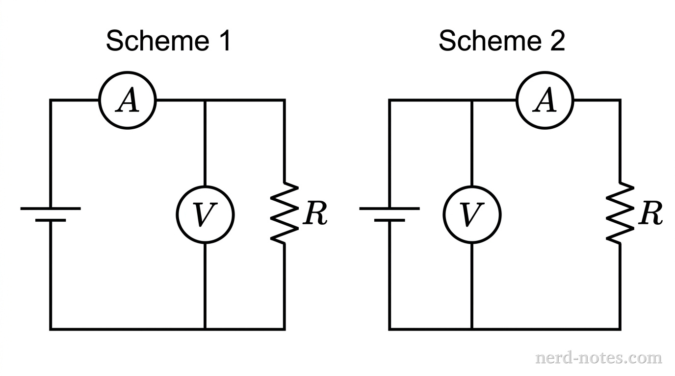
Scheme 1: The voltmeter is connected in parallel across \(R\), and the ammeter is connected in series with the power source to measure the total current entering the parallel combination.
Scheme 2: The ammeter is connected in series with \(R\), and the voltmeter is connected in parallel across the series combination of \(R\) and the ammeter.
For each scheme, the measured resistance is defined as \(R_{\text{meas}} = \dfrac{V}{I}\), where \(V\) is the voltmeter reading and \(I\) is the ammeter reading. Which scheme yields a measured resistance that is less than the true resistance \(R\), and what is the exact fractional error \(\dfrac{R_{\text{meas}} - R}{R}\) for that scheme?
| Choice | Scheme with \(R_{\text{meas}} < R\) | Fractional error \(\dfrac{R_{\text{meas}} - R}{R}\) |
|---|---|---|
| A | Scheme 1 | \(\dfrac{R_A}{R}\) |
| B | Scheme 1 | \(-\dfrac{R}{R + R_V}\) |
| C | Scheme 2 | \(-\dfrac{R}{R + R_V}\) |
| D | Scheme 2 | \(\dfrac{R_A}{R + R_A}\) |
Similar Questions
Tools for a 5
 AP aligned mock tests to help you get a 5.
With grading, adaptive explanations, and more.
Find a Quiz
Find, solve, and grade every AP FRQ ever.
Find an FRQ
Stuck on AP Physics C: E&M? Get unstuck with an AP specialist.1 to 1 tutors who know the exam inside out. Understand weeks of material in a single session.Find a Tutor
Learn AP Physics from scratch, quickly. This is the only course you'll need for the year.
A self-paced course with everything you need to get a 5. Trusted by over 15,000 students and 200+ schools. Learn fast, or we'll refund your purchase, backed by our 100% satisfaction guarantee.
Explore the Course
AP aligned mock tests to help you get a 5.
With grading, adaptive explanations, and more.
Find a Quiz
Find, solve, and grade every AP FRQ ever.
Find an FRQ
Stuck on AP Physics C: E&M? Get unstuck with an AP specialist.1 to 1 tutors who know the exam inside out. Understand weeks of material in a single session.Find a Tutor
Learn AP Physics from scratch, quickly. This is the only course you'll need for the year.
A self-paced course with everything you need to get a 5. Trusted by over 15,000 students and 200+ schools. Learn fast, or we'll refund your purchase, backed by our 100% satisfaction guarantee.
Explore the Course