All questions
AP Physics C: E&M
13.5 Circuits with Resistors and Inductors (LR Circuits)
13.4 Inductance
AdvancedMCQMathematicalConceptual14.5k
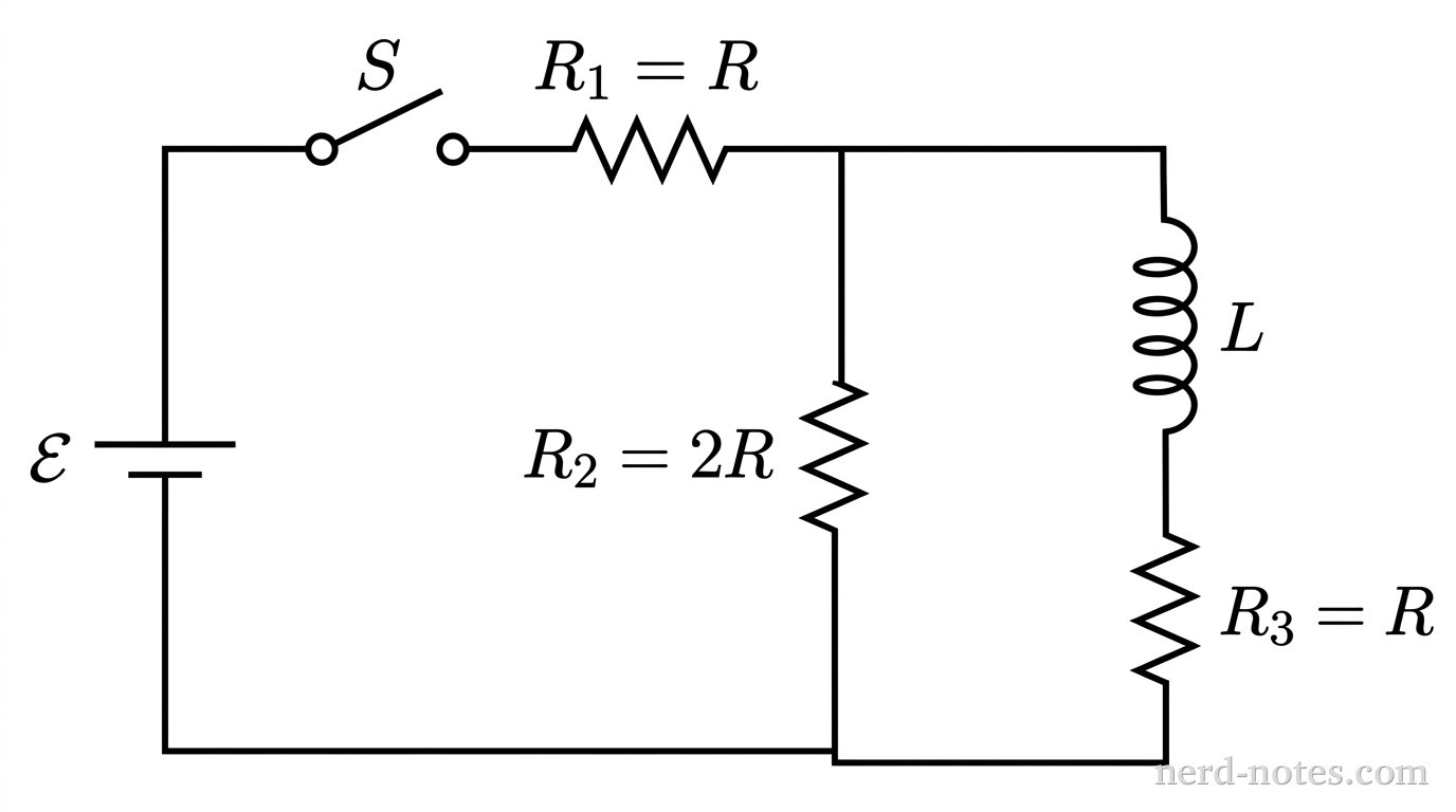
A rectangular schematic diagram of a multiloop DC circuit with three vertical parallel branches connected by top and bottom horizontal wires. The leftmost vertical branch contains an ideal DC battery labeled \(\mathcal{E}\) with the longer positive terminal line on top and shorter negative terminal line on the bottom. The top horizontal segment between the leftmost branch and the middle branch contains a switch labeled \(S\) and a resistor labeled \(R_1 = R\) in series. The middle vertical branch contains a resistor labeled \(R_2 = 2R\). The rightmost vertical branch contains an inductor shown as four rounded loops labeled \(L\) in series above a resistor labeled \(R_3 = R\). The bottom horizontal wire connects the bottoms of all three branches continuously. No other labels, lines, text, or axes appear.
Circuit schematic with battery, switch, resistors, and inductor.
In the circuit shown, an ideal battery of EMF \(\mathcal{E}\) is connected in series with an open switch \(S\) and a resistor of resistance \(R_1 = R\). In parallel with this combination are two branches: a middle branch containing a resistor of resistance \(R_2 = 2R\), and a right branch containing an ideal inductor of inductance \(L\) connected in series with a resistor of resistance \(R_3 = R\). The switch \(S\) is closed and the circuit is allowed to reach steady state. At time \(t = 0\), the switch \(S\) is suddenly opened. Immediately after the switch is opened, what is the magnitude of the induced EMF across the inductor?

Log In to Continue

Accounts are free! Log in to try this question, see explanations, save progress, and more!

Tools for a 5