
AP Physics 1
5.5 Rotational Equilibrium and Newton’s First Law in Rotational Form
5.3 Torque
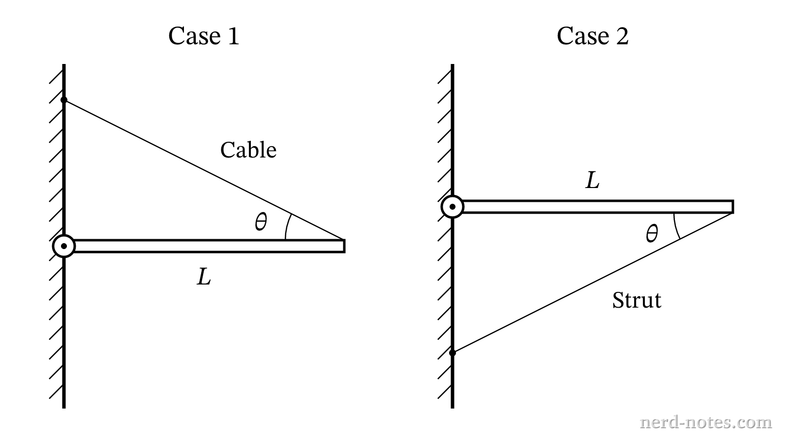
Which row in the table correctly compares the magnitude of the support force exerted on the right end of the beam, the magnitude of the total force exerted by the hinge on the beam, and the direction of the horizontal component of the force exerted by the hinge on the beam in Case 2 relative to Case 1?
| Support Force Magnitude in Case 2 | Total Hinge Force Magnitude in Case 2 | Direction of Horizontal Hinge Force in Case 2 | |
|---|---|---|---|
| (A) | Greater than in Case 1 | Greater than in Case 1 | Away from the wall |
| (B) | Equal to Case 1 | Equal to Case 1 | Toward the wall |
| (C) | Equal to Case 1 | Less than in Case 1 | Away from the wall |
| (D) | Less than in Case 1 | Equal to Case 1 | Toward the wall |
Similar Questions
Tools for a 5
 AP aligned mock tests to help you get a 5.
With grading, adaptive explanations, and more.
Find a Quiz
Find, solve, and grade every AP FRQ ever.
Find an FRQ
Elite Physics Tutoring with Jason.Fast, 1 to 1 help on AP Physics 1. Understand weeks of complex concepts in just one session.Book a SessionSee all our elite tutors
Learn AP Physics from scratch, quickly. This is the only course you'll need for the year.
A self-paced course with everything you need to get a 5. Trusted by over 15,000 students and 200+ schools. Learn fast, or we'll refund your purchase, backed by our 100% satisfaction guarantee.
Explore the Course