All questions
AP Physics 1
5.6 Newton’s Second Law in Rotational Form
5.4 Rotational Inertia
5.3 Torque
5.2 Connecting Linear and Rotational Motion
AdvancedFRQMathematicalProportional AnalysisConceptual23.3k
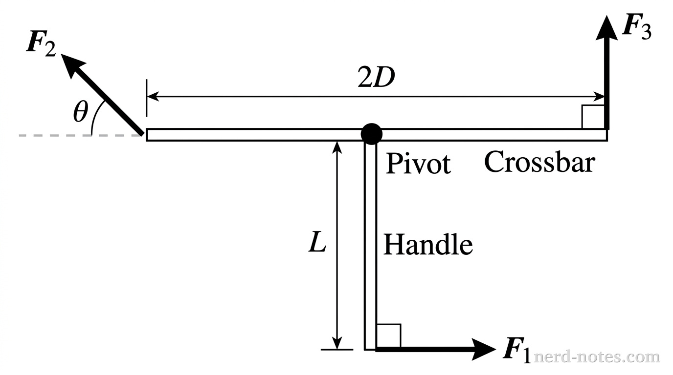
Overhead view of a T-shaped object on a flat surface. The T is oriented like an inverted capital 'T', with the horizontal line at the top and the vertical line extending downward. The horizontal line is labeled 'Crossbar' with total length '2D'. The vertical line is labeled 'Handle' with length 'L'. The intersection of the two lines is marked with a black dot labeled 'Pivot'. Three force arrows are shown: 1. At the bottom free end of the handle, an arrow labeled F_1 points horizontally to the right, with a right-angle symbol indicating it is perpendicular to the handle. 2. At the far left end of the crossbar, an arrow labeled F_2 points diagonally upward and to the left. A dashed line extends horizontally to the left from the crossbar, and the angle between this dashed line and the F_2 arrow is labeled \theta. 3. At the far right end of the crossbar, an arrow labeled F_3 points straight upward, parallel to the handle, with a right-angle symbol indicating it is perpendicular to the crossbar.
Figure 1. Overhead view of the structure and applied forces.
A rigid T-shaped structure lies at rest on a horizontal, frictionless surface. The structure is constructed from two uniform rods: a handle of mass \(M\) and length \(L\), and a crossbar of mass \(m\) and total length \(2D\). The handle is attached at one end to the exact center of the crossbar. The structure is pinned to the surface at the junction of the two rods by a frictionless vertical axis, allowing it to rotate freely in the horizontal plane.

The rotational inertia of a uniform rod of mass \(m_0\) and length \(\ell\) is \(\dfrac{1}{12}m_0\ell^2\) about its center and \(\dfrac{1}{3}m_0\ell^2\) about its end.

Log In to Continue

Accounts are free! Log in to try this question, see explanations, save progress, and more!

Tools for a 5